 Back to the homepage
The vehicle pictures are saved in library files (*.tvl) after being dragged as * .bmp or *.gif file into the vehicle list.
In the menu item "New", attributes for the images to be inserted can be pre-assigned.
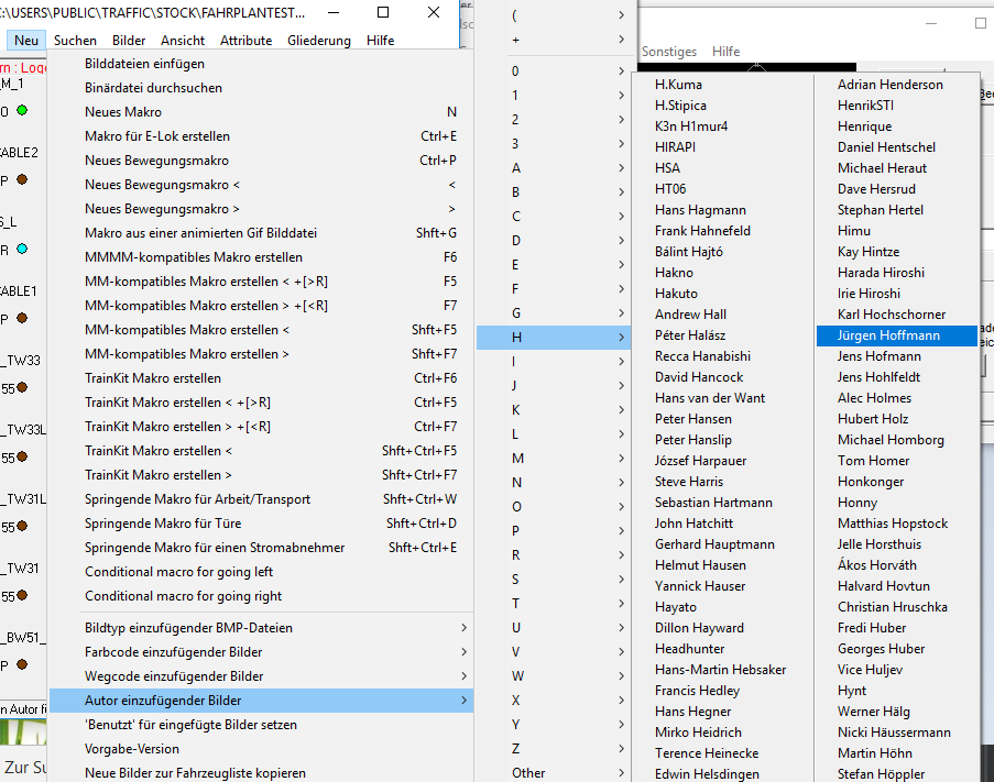
a. Preselect author for new images
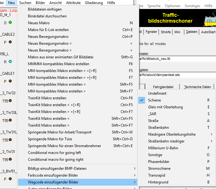
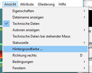
b. Set path
"Rail" is standard. If you want to insert for example electric locomotives, you can change the default setting to "rail with catenary", then you do not have to change it later.
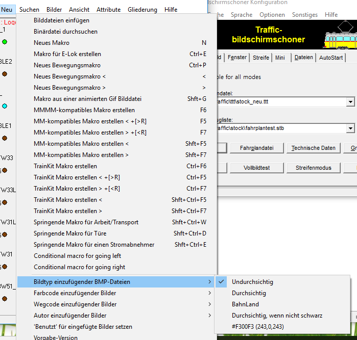
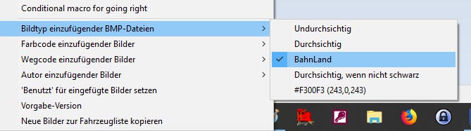
c. Set picture type
"Opaque" is standard. With Bahnland graphics you can set "Bahnland" directly, then the phase images are created automatically
Drag / drop the bitmap file into the vehicle list.
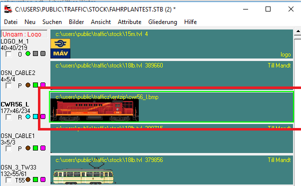
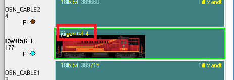
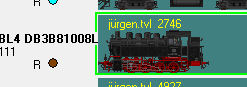
Mark picture (shows green border).
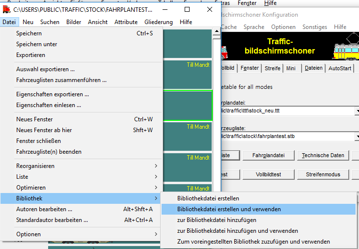
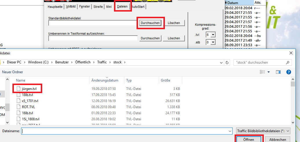
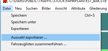
Select "File → Library → Create and use library file" in the menu.
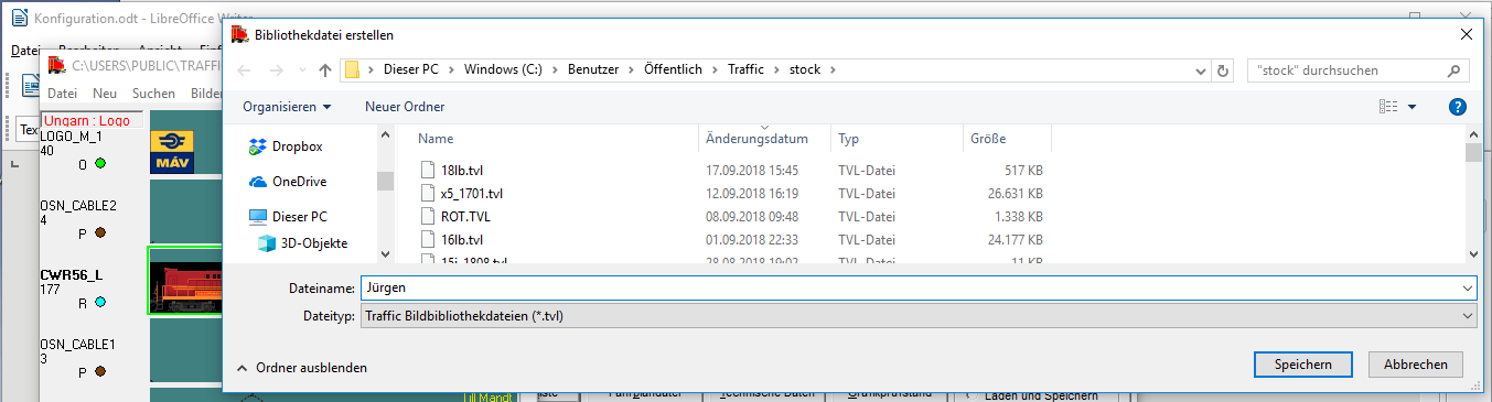
Enter file name and "Save"
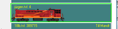
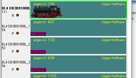
The file name can be displayed in the floor list.
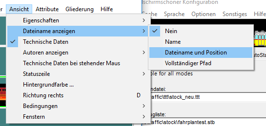
The file name of the new tvl is now displayed
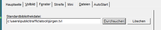
The new TVL can be selected as the standard library under Files..
The background color has to be changed to transparent.
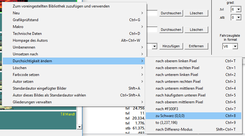
The picture is now transparent.
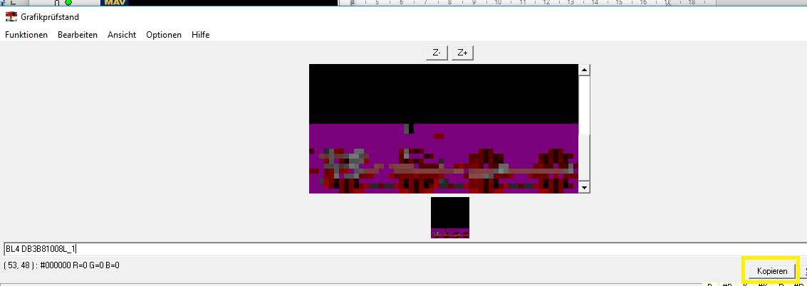
The background color can be selected here. With a color <> black one recognizes drawing errors.
Under "new" the image type "Bahnland" is selected to insert an image with phases.
The movement macro is generated automatically.
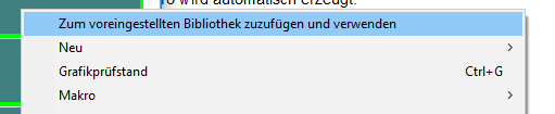
With the right mouse button and "Add to preset library and use", the images are transferred to the TVL.
The main picture is highlighted (green border). Use Shift and F9 to convert the phase images to difference mode. In this way, the phase images can be used for several images if there are no differences in the chassis in the variants.
Double-click to see pixel errors in the phase images.
Note: Sometimes the program crashes at this point, so save the vehicle list beforehand!
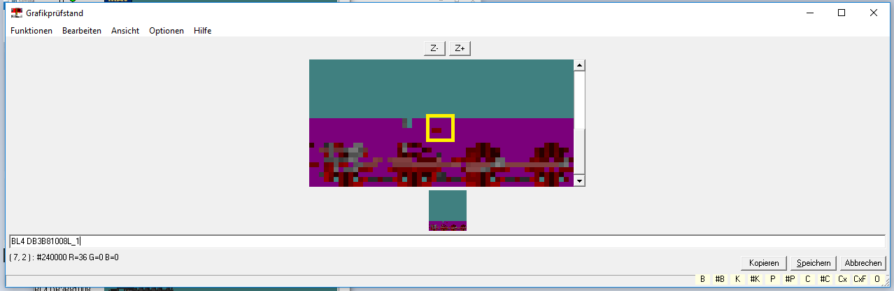
Double-click to see pixel errors in the phase images.
The following procedure for correction:
1. Close the graphics test bench
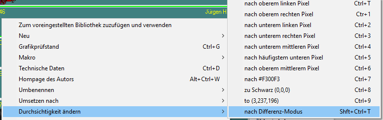
2. Set the background color to black
3. Open the graphics test bench again
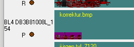
4. Copy the graphic and paste it into image processing.
55. Edit the graphic (paint over the missing pixel with the purple hue).
6. Change the image type of the images to be inserted back to "opaque".
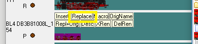
7. Drag and drop the corrected graphic onto the image in the vehicle list (replace).
8. Mark the picture entry and change the transparency to "black" with the right mouse button in the first step. Confirm the question about the TVL file with yes, the image is then automatically transferred to the TVL.
9. In the second step, change the transparency to "difference mode". The phase picture is now changed.
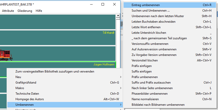
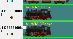
The image can be renamed with the right mouse button and Rename → Rename entry.
With "Rename phase pictures" phase pictures can be renamed easily.
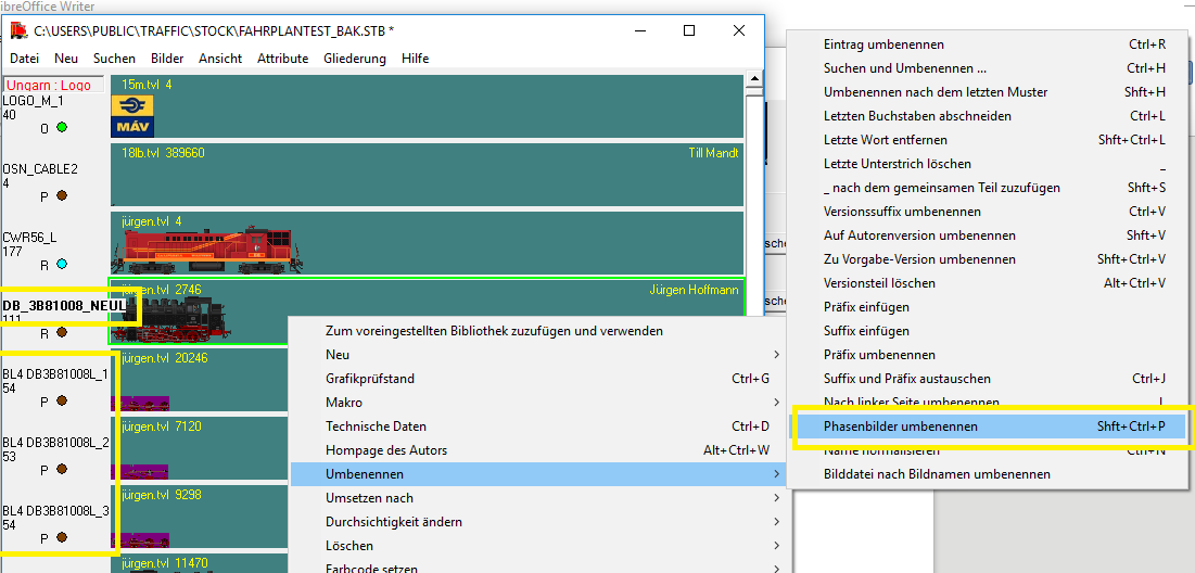
You will then receive the picture name of the main picture with the addition _1, _2…. .
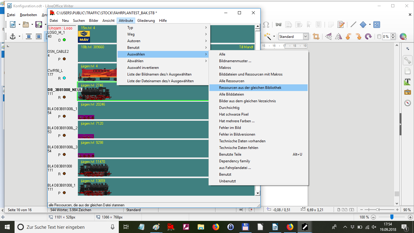
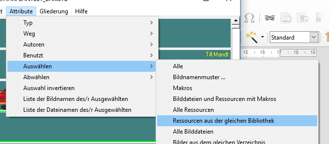
With "Select" → "Resources from the same library" all images of the TVL can be selected. B. to create your own vehicle list.
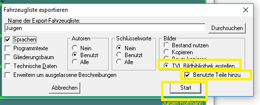
With the "Export selection" file, a new vehicle list "STB" can be created with the selected vehicles.
"TVL" - Create library also creates a new TVL file. Including the parts used. "Add used parts" causes z. B. Brake hoses from other TVL files can also be added. With "Start" the new file is created.
Sample image: „DRG_01004L“
Makro:
+>DRG_01002BL_1+5:3:DRG_01002BL_2+14:DRG_01002BL_3+34:1:DRG_01002L_4+5:DRG_01002L_5+5:DRG_01002L_6+14:DRG_01002L_7+/20[#D:L][N:B,BSG_D][O:DRG_2BBUML,106,21]
+/20 calculates the speed based on the driving wheel diameter 2m = 20.
Alternatively, you can also specify the speed in pixels:
+.2 = phase changes after two pixels. You can use it to move Spoke wheels of a coach..
[#D:L] causes the vehicle to drive ahead with the boiler (to the left). Vehicles with the boiler to the right must therefore receive the parameter [#D:R] erhalten. Tender locomotives, electric and diesel locomotives require the parameter normally does not.
[N:B,BSG_D] The picture has brake hoses not coupled on both sides. The macro places the image of a coupled brake hose (BSG_D) over the image when the car is attached. (N: neighbor, B = brake hose) The macro becomes active if the neighboring vehicle also has parameter B (clutch brake hose).
BSG_D only works if there are no steps in the picture.
If there are steps or other parts in front of the brake hoses, it is best to insert the pictures without hoses and use the macro [NB: B, BA8]. (NB = neighbor behind, the macro picture BA8 is not placed on but behind the picture. Example: DR_EAL5916CL
[O:DRG_2BBUML,106,21] The function O: sets the image DRG_2BBUML (yellow lettering at the position 106 pixels from the left, 21 pixels from below).
In addition to [O: xxx] there is also [OT: xxx] (overlay background). The overlay is not placed in front of the image, but behind it. With [OT: xxx] (overlay transparent) transparent images (like the transparent phase images generated above, color is purple)
Example picture:DB_3A82001
+29:DB_3A82001_1+29:1:DB_3A82001_2+32:1:DB_3A82001_3+/14[N:B,BSG_D][<MP:33,30,5,7]
[<MP: 33,30,5,7] causes the driver to be mirrored to the left when driving (looking to the left). 33.30 is the lower left position of the reflection, 5.7 the width and height of the mirrored surface. In the case of a locomotive with a boiler on the left, the reflection must be done accordingly with [> MP: 33,30,5,7].
Insert the pantograph that has been lowered:
Example picture: DBAG_140_744
:DBAG_140_062:30:26[ED:140PD,17][ED:140PD,110][N:B,BA8][O:DB_141_230L,80,21]
Das Bild hat zwei aufgebügelte Stromabnehmer [ED:140PD,17] bewirkt, dass an der Position 17 Pixel von links das Bild 140PD (abgebügelter Stromabnehmer) eingefügt wird.
The image has two ironed pantographs [ED: 140PD, 17], so that the image 140PD (ironed pantograph) is inserted at position 17 pixels from the left.
It is often better to insert the ironed pantographs, as the pantographs cover roof structures when ironed. So you can use a pantograph image for all positions. Ironed-on pantographs often have to be drawn individually for each position because the roof structures appear in the background. An ironed pantograph can be inserted with [E:140xx,17] .
Mirroring pantograph:
Pantographs can be mirrored if the image contains an ironed and an ironed pantograph. Example image: FS_E424XMPRL
[EM:109,39,33][NM:B,5,4,4][BC:4,30]
[EM:109,39,33] 109 is the left position of the iron-on current collector, 39 is the lower edge of the surface to be mirrored, 33 the width of the surface.
Insert open transitions (end of train)
Both ends of the car must have a closed bellows.
Example picture: DB_4A_WGUE831
[N:#P,#DB_FBE37L,12][NB:B,BA1]
[N:#P,#DB_FBE37L,12] causes the picture DB_FBE37L (transition end of train) to be inserted 12 pixels above the rail. The images for the transitions must not overlap with the images for brake hoses.
# DB_FBE37L The diamond has the effect that the image is mirrored. Otherwise, the transition would be displayed the wrong way round. H. The picture was drawn upside down.
N: #P: The diamond has the effect that the image is used as a non-closed transition.
Conversely, if the original image is drawn with transitions that are not closed and a closed transition is to be inserted as a macro, the macro must be used without a diamond, ie: [N: P, # DB_FBxxx, 12]
Make open transitions (train ends) transparent
For example german Apron cars do not need an additional picture for the transition at the end of the train.
The bellows can easily be replaced by a transparent surface (stripes).
Example image: DSG_WR4UE39L
[NB: B, BA8] [NC: P, 1,22,12]
The macro [NC: P, 1,22,12] causes an area with a width of 1 and a height of 22 to be displayed transparently from a position 12 pixels below (above the buffers) at the end of the train.
If a carriage with a rubber bead connection is to be coupled with a carriage with bellows, the macro [NT: P] must be inserted in the carriage with rubber bead transition.
(especially for cars in epochs 3 and 4)